- Get link
- Other Apps
- Get link
- Other Apps
As those who read my previous article about M590 GSM/GPRS module know, it's not very reliable for GPRS operation. Recognizing this downside of M590s, I still wanted to use them (heaps of
UPDATE 25 Apr. 2018:
Essential documents for M590
Neoway M590E GPRS Module Hardware User Guide v 1.0
Neoway M590 Hardware Design Manual Version 1.1
Neoway M590 AT command sets v. 3.0
This blog post is a part of series about really cheap GSM/GPRS module Neoway M590:
- Neoway M590 GPRS Tutorial: sending and receiving files from/to SD card
- SMS GPS-tracker with Neoway M590 and ublox NEO-6 part 1. Gathering parts and testing
- SMS GPS-tracker with Neoway M590 and ublox NEO-6 part 2. Assembling the device
Heating part:
Beside that I only had to source a 1 m. piece of round ventilation duct and a fan. The heater has to be positioned roughly at the center of duct. I also sawed out rectangular pieces from the duct so that the plastic fan wouldn't melt, to further protect it from overheating I installed an NC thermal switch that opens when the temperature is around 90°C.
You should be able to easily replicate my setup just by looking at the pictures below:
- You can use anything that won't melt for suspension - steel or copper wire is what you'll probably find lying around in no time.
- Hanging the heater was the dumbest thing done in this project. When you heat air it goes UP whereas the cold air stays down below. The fastest and the most efficient way to heat air is to install this on the floor.
Electronics part:
I also went full ghetto with the enclosure, which is a plastic box from some power tool painted black. It gives off the air of something quickly put together from scraps and that's what I like about it - I'm all about improvisation :-)
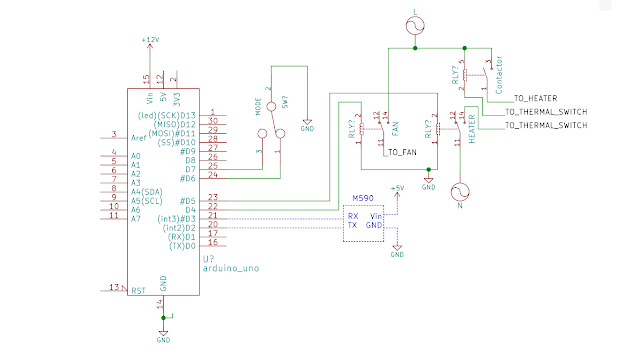
Schematics:
- Arduino UNO (can be a nameless clone, make sure to donate to Arduino foundation if you buy one)
- Neoway M590 kit (or assembled module)
- Two 12V relay modules
- Two copper bus bars
- Contactor with AC coil. You can buy one from China, if you dare😈
- 3-position switch (ON-OFF-ON). Something rugged like this or this
- 12V PSU and 5V PSU. You can get them separate: 12V 1A or greater curent rating and 5V 2A or greater current rating, or try to find something combined
| Ready to be connected! |
|
|
|
|---|---|
|
|
Arduino sketch:
I'm using an official Arduino Bounce library for debouncing (I'm that lazy). The heater has 3 modes: ON, OFF and AUTO, which are switched by the switch on the main panel. When switched off, the controller turns off the heater but lets fan blow off the heat for a preset time (120 seconds in my case). In AUTO mode you can send SMS to switch the heating on or off, but there's a timeout of 3 hrs. for safety reasons. So, if I were to switch on the heater and forget about it completely it would not waste tons of energy waiting for me to come to the garage.
Seeing how impressed my friends were when they saw this thing controlled by an SMS I immediately felt it was worth making. And with cold season coming it's going to become my greatest asset.
|
|
|
|---|---|
UPDATE:
After a month of use I decided this heater needs to be turned on and off on a schedule, so I added an RTC module (based upon DS1302 chip). Nothing much to add to the schematics - just hook up 5V from Arduino to RTC and connect 3 data lines to pins 7-9.This is the library I used to interface the chip. Not sure if it's unreliable library or something I messed up while connecting the module, but most of the time rtc.time() function spews out some date in year 2011, so I had to poll it to get the right date.
See updated code below:

Comments
Post a Comment